数字逻辑与系统设计设计报告
项目内容
题目:8位乘法器
输入为两个8位有符号数或无符号数,输出16位相乘结果
采用Booth算法对乘法转化为部分和求和
采用Wallace算法减少部分和求和时所使用的全加器数量
编译器及测试仿真环境
win11系统,EDA环境为Quartus,EDA软件版本为18.0,验证板卡为DE10Lite,波形仿真软件为Modelsim,软件版本为SE-64 2020.4
该8位乘法器设计特点
本文采用Radix-4 Booth乘法器对乘法运算化简为4个部分和求和;同时对化简后的部分和采用Wallace树算法进行加速运算,减少全加器和半加器数量的使用。
Radix-4 Booth算法
Booth算法原理:
对于8位有符号数A可以表示为如(1)式所示,其中用A i A_{i} A i i i i
\begin{align}
A = -A_{7}\times 2^{7} + \sum_{i=0}^{6} A_{i} \times 2^{i}
\end{align}
同时考虑对A i A_{i} A i
\begin{align}
A_{i} = A_{i} \times ( 2^{i+1} - 2\times 2^{i } )
\end{align}
进而可以对8位有符号数A进行如下分解,补充定义A − 1 = 0 A_{-1}=0 A − 1 = 0
\begin{align}
A =& -A_{7}\times 2^{7} + \sum_{i=0}^{6} A_{i} \times 2^{i} \notag\\
=& -A_{7} \cdot 2^{7} + A_{6} \cdot 2^{6} + A_{5} \cdot ( 2^{6} - 2 2^{4} ) \notag\\
& + A_{4} \cdot ( 2^{5} - 2\times 2^{3} ) + ... + A_{0} \cdot 2^{0} \notag\\
=& (-2A_{7} + A_{6} + A_{5})\cdot 2^{6} + (-2A_{5} + A_{4} + A_{3})\cdot 2^{4} \notag\\
&+ (-2A_{3} + A_{2} + A_{1})\cdot 2^{2} + (-2A_{1} + A_{0} + A_{-1})\cdot 2^{0} \notag\\
=& Coef_{3}\cdot 2^{6} + Coef_{2}\cdot 2^{4} + Coef_{1}\cdot 2^{2} + Coef_{0}\cdot 2^{0} \\
\end{align}
因此A × B A\times B A × B
\begin{align}
A\times B=&Coef_{3}\cdot 2^{6}\times B + Coef_{2}\cdot 2^{4}\times B \notag\\
&+ Coef_{1}\cdot 2^{2}\times B + Coef_{0}\cdot 2^{0}\times B
\end{align}
可以发现2 i , i = 0 , 2 , 4 , 6 2^{i},i=0,2,4,6 2 i , i = 0 , 2 , 4 , 6 A i , A i + 1 , A i + 1 A_{i},A_{i+1},A_{i+1} A i , A i + 1 , A i + 1 C o e f Coef C o e f C o e f Coef C o e f A i A_{i} A i A i + 1 A_{i+1} A i + 1 A i + 1 A_{i+1} A i + 1
A i + 1 A_{i+1} A i + 1 A i A_{i} A i A i − 1 A_{i-1} A i − 1 C o e f Coef C o e f
0
0
0
0
0
0
1
1
0
1
0
1
0
1
1
2
1
0
0
-2
1
0
1
-1
1
1
0
-1
1
1
1
0
故可以将两个8位有符号数A,B的乘积A × B A\times B A × B C o e f Coef C o e f C o e f Coef C o e f
1
2
3
4
5
6
7
8
9
10
11
12
13
p <= 16'd0 ; M <= {{8 {multiplicand[7 ]}},multiplicand}; M_shadow <= {{8 {~multiplicand[7 ]}},~multiplicand+1'b1 }; M2 <= {{8 {multiplicand[7 ]}}, multiplicand << 1 }; M2_shadow <= {{8 {~multiplicand[7 ]}}, (~multiplicand+1'b1 ) << 1 }; N <= {multiplier,1'b0 }; shift_num <= 4'd0 ; i <= i + 1'b1 ;
同时定义RSTn和done信号用于表征乘法运算的开始和结束,同时利用case语句实现对4个部分和的逐次表征,并利用多个i f if i f C o e f Coef C o e f
1
2
3
4
5
6
7
8
9
10
11
12
13
14
15
16
17
18
19
20
21
22
23
24
25
26
27
28
29
30
31
32
33
34
35
36
37
38
39
40
41
42
43
44
45
46
47
48
49
50
51
52
53
54
55
56
57
58
59
60
61
62
63
64
65
66
67
68
69
70
71
72
73
74
75
76
77
78
79
80
81
82
83
84
85
86
87
88
89
90
91
92
93
module booth_multiply#( parameter DATAWIDTH = 8 ) ( input CLK, input RSTn, input START, input [ DATAWIDTH - 1 : 0 ] A, input [ DATAWIDTH - 1 : 0 ] B, output [ DATAWIDTH * 2 - 1 : 0 ] RESULT, output Done ); reg [ DATAWIDTH - 1 : 0 ] i;reg [ DATAWIDTH * 2 : 0 ] P;reg [ DATAWIDTH - 1 : 0 ] A_reg;reg [ DATAWIDTH - 1 : 0 ] A_bm;reg [ DATAWIDTH - 1 : 0 ] N;reg [ DATAWIDTH * 2 : 0 ] result_reg;reg isDone;always @ ( posedge CLK or negedge RSTn )begin if (!RSTn) begin i <= 0 ; P <= 0 ; A_reg <= 0 ; A_bm <= 0 ; result_reg <= 0 ; N <=0 ; isDone <= 0 ; end else if (START) begin case (i) 0 :begin A_reg <= A; A_bm <= ~A + 1'b1 ; P <= { 8'd0 , B, 1'b0 }; i <= i + 1'b1 ; N <= 0 ; end 1 :begin if (N == DATAWIDTH) begin N <= 0 ; i <= i + 2'b10 ; end else if (P[1 :0 ] == 2'b00 | P[1 :0 ] == 2'b11 ) begin P <= P; i <= i + 1'b1 ; end else if (P[1 :0 ] == 2'b01 ) begin P <= {P[16 :9 ] + A_reg,P[8 :0 ]}; i <= i + 1'b1 ; end else if (P[1 :0 ] == 2'b10 ) begin P <= {P[16 :9 ] + A_bm,P[8 :0 ]}; i <= i + 1'b1 ; end end 2 : begin P <= {P[16 ],P[16 :1 ]}; N <= N + 1'b1 ; i <= i - 1'b1 ; end 3 : begin isDone <= 1 ; result_reg <= P; i <= i + 1'b1 ; end 4 : begin isDone <= 0 ; i <= 0 ; end endcase end end assign Done = isDone;assign RESULT = result_reg[16 :1 ];endmodule
仿真测试与波形查看
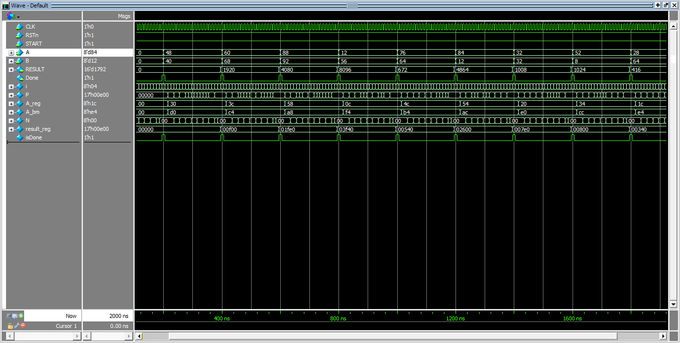
1 2 3 4 5 6 7 8 9 10 11 12 13 14 15 16 17 18 19 20 21 22 23 24 25 26 27 28 29 30 31 32 33 34 35 36 37 38 39 40 41 42 43 44 45 46 47 48 49 50 51 52 53 54 55 56 57 58 59 60 61 62 63 64 65 66 67 68 69 70 71 72 73 74 `timescale 1ns / 1ps module tb_booth_multiply;parameter PERIOD = 10 ;parameter DATAWIDTH = 8 ;reg CLK = 0 ;reg RSTn = 0 ;reg START = 0 ;reg [ DATAWIDTH - 1 : 0 ] A = 0 ;reg [ DATAWIDTH - 1 : 0 ] B = 0 ;wire [ DATAWIDTH * 2 - 1 : 0 ] RESULT ;wire Done ;initial begin forever #(PERIOD/2) CLK=~CLK; end initial begin #(PERIOD) RSTn = 1 ;START = 1 ; end booth_multiply #( .DATAWIDTH ( DATAWIDTH )) u_booth_multiply ( .CLK ( CLK ), .RSTn ( RSTn ), .START ( START ), .A ( A [ DATAWIDTH - 1 : 0 ] ), .B ( B [ DATAWIDTH - 1 : 0 ] ), .RESULT ( RESULT [ DATAWIDTH * 2 - 1 : 0 ] ), .Done ( Done ) ); initial begin A = 2 ; B = 4 ; #200 A = 3 ; B = 5 ; #200 A = -4 ; B = 6 ; #200 A = 123 ; B = -56 ; #200 A = 99 ; B = 44 ; #200 A = -34 ; B = -66 ; #200 A = 23 ; B = 12 ; #200 A = 111 ; B = 100 ; #400 $finish ; end endmodule
同时仿真波形如下图1所示:
同时如果检测该乘法器对所有8位有符号数相乘的可行性,则上述在testbench中手动设置乘数和被乘数的方法则会过于麻烦,因此也可以考虑如下方法来设置随机数仿真。
随机数型乘法器仿真testbench代码可补充如下:
1 2 3 4 5 6 7 8 9 10 11 12 13 14 15 16 17 18 19 20 21 22 23 24 25 26 27 28 29 30 31 32 33 34 35 36 37 38 39 40 41 42 43 44 45 46 47 48 49 50 51 52 53 54 55 56 57 58 59 60 61 62 63 64 65 66 67 68 69 70 71 `timescale 1ns / 1ps module tb_booth_multiply;parameter PERIOD = 10 ;parameter DATAWIDTH = 8 ;reg CLK = 0 ;reg RSTn = 0 ;reg START = 0 ;reg [ DATAWIDTH - 1 : 0 ] A = 0 ;reg [ DATAWIDTH - 1 : 0 ] B = 0 ;wire [ DATAWIDTH * 2 - 1 : 0 ] RESULT ;wire Done ;initial begin forever #(PERIOD/2) CLK=~CLK; end initial begin #(PERIOD) RSTn = 1 ;START = 1 ; end booth_multiply #( .DATAWIDTH ( DATAWIDTH )) u_booth_multiply ( .CLK ( CLK ), .RSTn ( RSTn ), .START ( START ), .A ( A [ DATAWIDTH - 1 : 0 ] ), .B ( B [ DATAWIDTH - 1 : 0 ] ), .RESULT ( RESULT [ DATAWIDTH * 2 - 1 : 0 ] ), .Done ( Done ) ); initial begin A = 2 ; B = 4 ; #200 A = 3 ; B = 5 ; #200 A = -4 ; B = 6 ; #200 A = 123 ; B = -56 ; #200 A = 99 ; B = 44 ; #200 A = -34 ; B = -66 ; #200 A = 23 ; B = 12 ; #200 A = 111 ; B = 100 ; #400 $finish ; end endmodule
但verilog中的随机数生成依赖于其中的种子seed,故我们可以直接利用乘数A的值做为下一次random生成所需的种子,这样我们就可以不用每次仿真调整随机数了,为我们测试乘法器的可靠性和鲁棒性带来方便。即将initial begin里的语句 改成如下所示即可:
1
2
3
4
5
6
7
8
9
initial begin A = 0 ; B = 0 ; repeat (10 ) begin #200 A = {$random (A)}%100 ; B = {$random (A-1 )}%100 ; end #5 $finish ; end
同时仿真波形如下图2-图3所示:
Wallace算法
本文采用Wallace算法实现对8位无符号数乘法器的加速,实现了部分和求和时所使用的全加器数量的减少。
全加器与半加器 :全加器是一个三输入两输出的逻辑单元,它可以同时处理两个数据输入位以及一个来自前一级的进位输入,并产生一个本级的和输出以及一个向后一级传递的进位输出。而半加器仅处理两个数据输入位而不考虑前一级的进位,因此它的结构相对简单。
对于8位无符号数相乘,会出现8个部分积,故我们采用4:2压缩器,将其先压缩为4个部分积,再压缩为2个部分积
1 2 3 4 5 6 7 8 9 10 11 12 13 14 15 16 17 18 19 20 21 22 23 24 25 26 27 28 29 30 31 32 33 34 35 36 37 38 39 40 41 42 43 44 45 46 47 48 49 50 51 52 53 54 55 56 57 58 59 60 61 62 63 64 65 66 module wallace(x, y, out);parameter size = 8 ; input [size-1 :0 ] x, y; output [2 *size-1 :0 ] out;wire [size*size-1 :0 ] a; wire [1 :0 ] b0, b1; wire [1 :0 ] c0, c1, c2, c3; wire [5 :0 ] add_a, add_b; wire [6 :0 ] add_out; wire [2 *size-1 :0 ] out; assign a = {x[3 ], x[2 ], x[3 ], x[1 ], x[2 ], x[3 ], x[0 ], x[1 ],x[2 ], x[3 ], x[0 ], x[1 ], x[2 ], x[0 ], x[1 ], x[0 ]}& {y[3 ], y[3 ], y[2 ], y[3 ], y[2 ], y[1 ], y[3 ], y[2 ],y[1 ], y[0 ], y[2 ], y[1 ], y[0 ], y[1 ], y[0 ], y[0 ]}; module compressor4_2(i1,i2,i3,i4,cin,c_out,C,S)input i1,i2,i3,i4,cin;output C,S;wire s_temp;assign {cout,s_temp} = i1+i2+i3;assign {C,S} = cin+s_temp+i4;endmodule module pp_compressor4_2(input [15 :0 ] pp_in1,input [15 :0 ] pp_in2,input [15 :0 ] pp_in3,input [15 :0 ] pp_in4,output [15 :0 ] C,output [15 :0 ] S); wire [15 :0 ] C_comb;wire [15 :0 ] S_comb;wire [15 :0 ] C_temp;wire [16 :0 ] C_temp_append_0;assign C_temp_append_0 = {C_temp,1'b0 };genvar i;generate for (i=0 ;i<16 ;i=i+1 ) begin :compressor4_2_inst compressor4_2 u_compressor4_2( .i1 (pp_in1[i]), .i2 (pp_in2[i]), .i3 (pp_in3[i]), .i4 (pp_in4[i]), .cin (C_temp_append_0[i]), .cout (C_temp_append_0[i+1 ]), .C (C_comb[i]), .S (S_comb[i]) ); end endgenerate assign S=S_comb;assign C={C_comb[14 :0 ],1'b0 };endmodule
1
2
3
4
5
6
7
8
9
10
11
12
13
14
15
16
17
18
19
20
21
22
23
24
25
26
27
28
29
30
31
32
33
34
35
36
37
38
39
40
41
42
module (input [7 :0 ] a,input [7 :0 ] b,output [15 :0 ] S); wire [15 :0 ] partial_res0;wire [15 :0 ] partial_res1;wire [15 :0 ] partial_res2;wire [15 :0 ] partial_res3;wire [15 :0 ] partial_res4;wire [15 :0 ] partial_res5;wire [15 :0 ] partial_res6;wire [15 :0 ] partial_res7;wire [15 :0 ] C1;wire [15 :0 ] C2;wire [15 :0 ] C3;wire [15 :0 ] S1;wire [15 :0 ] S2;wire [15 :0 ] S3;assign partial_res0={8'b0 ,b*a[0 ]};assign partial_res1={7'b0 ,b*a[1 ],1'b0 };assign partial_res2={6'b0 ,b*a[2 ],2'b0 };assign partial_res3={5'b0 ,b*a[3 ],3'b0 };assign partial_res4={4'b0 ,b*a[4 ],4'b0 };assign partial_res5={3'b0 ,b*a[5 ],5'b0 };assign partial_res6={2'b0 ,b*a[6 ],6'b0 };assign partial_res7={1'b0 ,b*a[7 ],7'b0 };pp_compressor4_2 u1(partial_res0,partial_res1,partial_res2,partial_res3,C1,S1); pp_compressor4_2 u2(partial_res4,partial_res5,partial_res6,partial_res7,C2,S2); pp_compressor4_2 u3(C1,S1,C2,S2,C3,S3); assign S = C3+S3;